
The source of radiation in the case of infrared beamlines is the bending magnet. The extraction of infrared radiation from synchrotron radiation is done using the first flat mirror (M1), which will be located in the VK1 vacuum chamber in which the electron beam circulates. The planned distance of the M1 mirror from the beginning of the magnetic field is about 800 mm while maintaining a distance from the electron beam equal to 14 mm will allow us to obtain the distribution of infrared radiation intensity on the M1 mirror shown in Figure 1B.
Infrared radiation has two real sources: the Bending Magnet Radiation (BMR) and the edge of the field at the entrance to the magnet (ER - Edge Radiation). Figure 1 shows the distribution of infrared radiation intensity for two wavelengths: 10 μm (1000 cm-1) and 200 μm (50 cm-1). BMR is visible in Figure 1B (λ = 10 μm) in the form of horizontal stripes with two intensity maxima. Whereas ER is visible in the form of characteristic high-intensity rings, it is the result of interference from infrared radiation emitted by an electron located in two different magnetic fields - at the beginning and end of a straight section. For a wavelength of 200 μm, the predominant input has ER intensity, while for a 10 μm wavelength the input of both BMR and ER is visible.
To prevent the M1 mirror from being damaged by high-energy X-rays, it will have a horizontal gap in position 0 (Figure 1B) with a width of 2 mm, which will allow the high-energy radiation to pass to the appropriate absorber. Infrared radiation reflected from the M1 mirror at the right angle will be directed outside the VK1 chamber to a further system of five mirrors - M2 to M6 (Figure 1A) to ensure, correction of chromatic aberrations and direct the infrared beam towards the exit from the storage ring and to the end stations, by applying the appropriate curvature of the mirrors and reflection at the right angle.
In the planned optical system there will be a diamond window (CVD) between the M4 mirror and the M5 mirror in the place of the first focus of the infrared beam. The entire optical system up to the CVD window will be in a high vacuum system, corresponding to the vacuum held in the ring. Behind the CVD window, the beam will be guided in a low vacuum. The total intensity of the infrared beam at a distance of 5 m (approximate position of workstations relative to the M6 mirror) from the M6 mirror is shown in Figure 1C.
Figure 1. CIRI beamline construction.
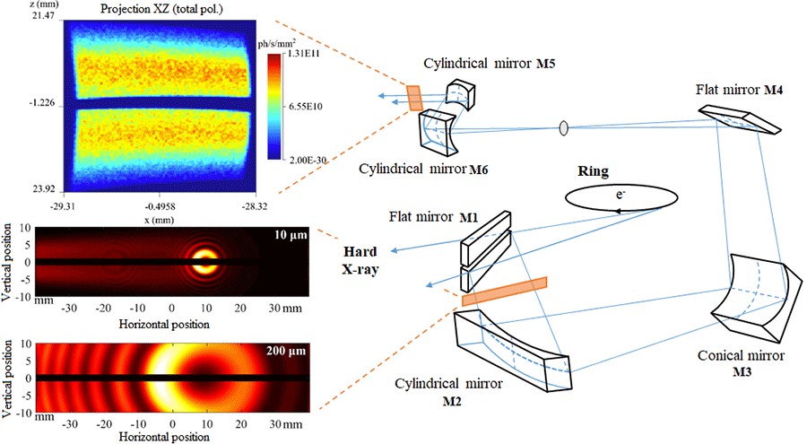
Figure 2. Optical system diagram.