
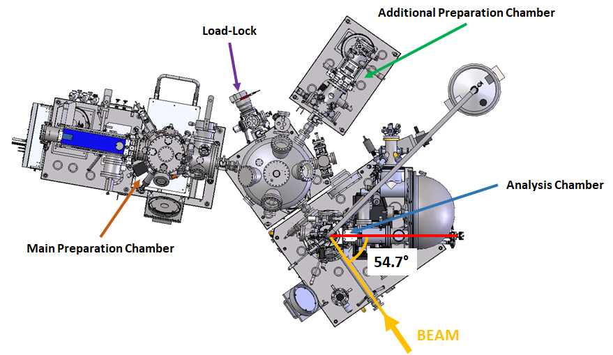
Fig. 1. Top view of the PHELIX end station model with marked measurement geometry and UHV system components.
The PHELIX end-station enables a wide range of spectroscopic and absorption studies characterized by different surface sensitivity. In addition to collecting standard high-resolution spectra, it allows, for example, to map the band structure in three dimensions and to detect the spin in three dimensions.
- analysis chamber with hemispherical photoelectron energy analyzer with resolution ~1 meV, 3D spin detector VLEED-type with spin rotator, total fluorescence detector and additional X-ray source of radiation enabling operation without a beam,
- well-equipped preparation chamber with effusion cells and EBVs for in situ thin layers deposition with precise control of their thickness, LEED diffractometer, leak valves enabling operation with various gases and a sample stage allowing samples to be heated up to 2000°C,
- additional preparation chamber adapted for reactions with gases at a maximum pressure of 800 mbar,
- crystal cleaver chamber allowing to expose atomically smooth surfaces under ultra-high vacuum conditions,
- installation enabling the connection of vacuum suitcases (Ferrovac or other).
Techniques available
- Angular-integrated photoelectron spectroscopy measurements: XPS, resonant photoemission (ResPES)
- Angle-resolved photoelectron spectroscopy measurements: soft X-rays (SX-ARPES), circular dichroism (CD-ARPES), spin-resolved (SR-ARPES)
- Absorption spectroscopy (XAS) measurements in the sample current (TEY) and total fluorescence (TFY) mode.
By using a spin rotator before the entrance of the spin detector, all three spin components can be accessed. The magnetic lens rotates the spin components perpendicular to the direction of electron travel through the measuring system without affecting the parallel component (fig. 2). The angles of rotation of the perpendicular components are +/- 45° (fig. 2 and 3). By using the same value of the angle of rotation with the opposite sign, the value of the solenoid current remains the same, while the direction of the current changes to the opposite. This allows the electrons to maintain the same trajectory and focal point in the spin detector.
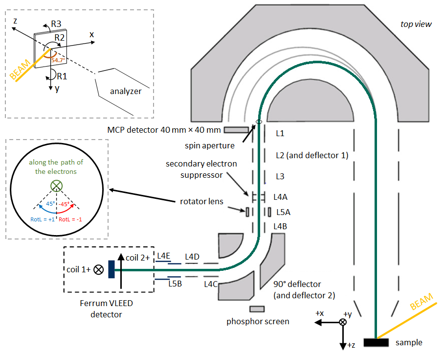
Fig.2. Top view of the measurement setup scheme.
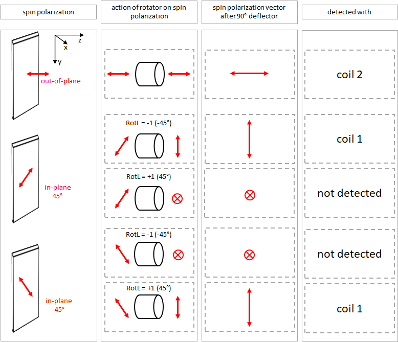
Fig. 3. Scheme showing the principle of operation of the spin rotator installed in front of the VLEED spin detector.
Sample holders
Samples measured at PHELIX beamline are mounted on the flag style sample holders (Omicron standard plate). PTS adapters are used to transfer flag styles within the UHV system (except of the analysis chamber). Due to this configuration and the construction of the analysis chamber manipulator sample station, the opposite edges 2 mm wide of the flag style holder must remain free on each side. In case of self-made flag style holders, please pay special attention to the shape of the grip (rounded corners) and the length of the connection between the grip and the part on which the samples are mounted - due to the construction of the wobble stick manipulator that transfers flag style holders from PTS adapters to the measuring manipulator station, these dimensions must be exactly as described in the drawing.
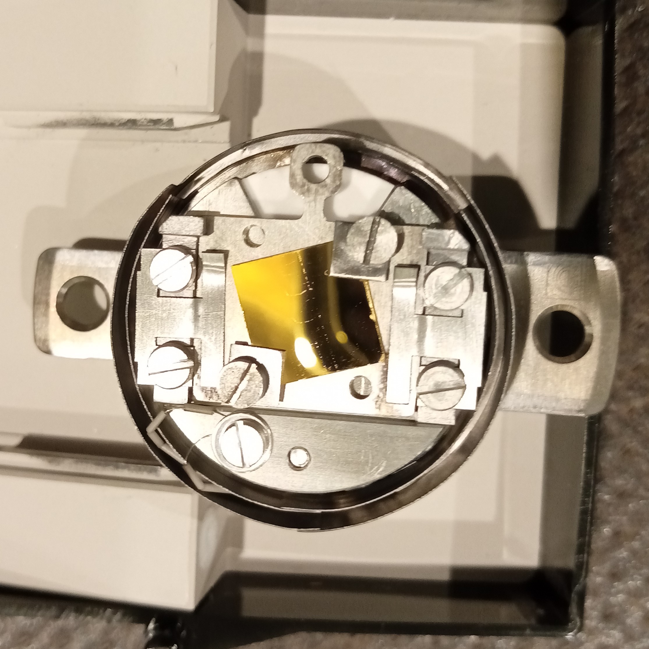
Fig. 4. Photo of the flag style sample holder with the Au (111) single crystal mounted on the PTS adapter.
If any technical questions arise during the planning of the experiment (sample assembly, experiment conditions, end-station capabilities, etc.), please contact the beamline scientists before submitting a proposal.
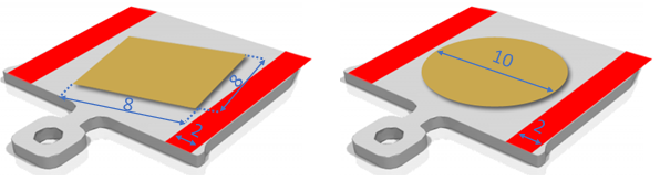
Fig. 5. Acceptable sample size and the size of the margin on the edges of the flag style holder, values are given in millimeters.