
Experimental Station
The experimental station at PIRX beamline is a UHV system outfitted with two-chambers: a spectroscopy measurement chamber equipped with LHe cryostat and electromagnet and preparation chamber for in-situ experiments. The two chambers together with a load lock are connected by a sample transfer system that operates manually under ultra-high vacuum.
Figure 6. A model of the end station, which consists of two chambers (spectroscopy and preparation) and a load lock.
Sample requirements
- UHV compatible;
- Samples (powder and bulk) fitting a standard flag-style (an Omicron type plate) sample holder;
- Should not charge under X-ray illumination.
Measurement conditions
- Total electron yield (TEY) detection mode, giving a sampling depth of several nm;
- Total (TFY) and partial (PFY) fluorescence mode using an SDD fluorescent detector, giving a sampling depth of several hundreds of nm;
- The partial electron yield (PEY) detection mode, giving a sampling depth of a few nm for samples with low electrical conductivity using a MCP (multichannel plates) with retarding voltage. Detection mode is available after prior consultation with the beamline scientists;
- Available external magnetic field of 0-140 mT parallel to the photon beam;
- Available sample temperature during measurements: 20-570 K for experiments in high and ultra high vacuum conditions. In the preparation chamber: 150 K – 2000 K.
Sample holder
The drawing below shows the Omicron-type plate (flag style) used as a sample holder. The marked space determines the available area of sample holder for sample mounting. Minimum size of the sample is limited by the beam spot size at end station, which is 250 µm x 40 µm.
Please remember that for temperature dependent experiment (cooling or heating) the sample installation using clamps, wires or screws is required.
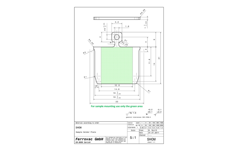
Figure 7. The drawing of omicron-type plate/ flag style holder (dimensions are in mm) with marked available area for sample.
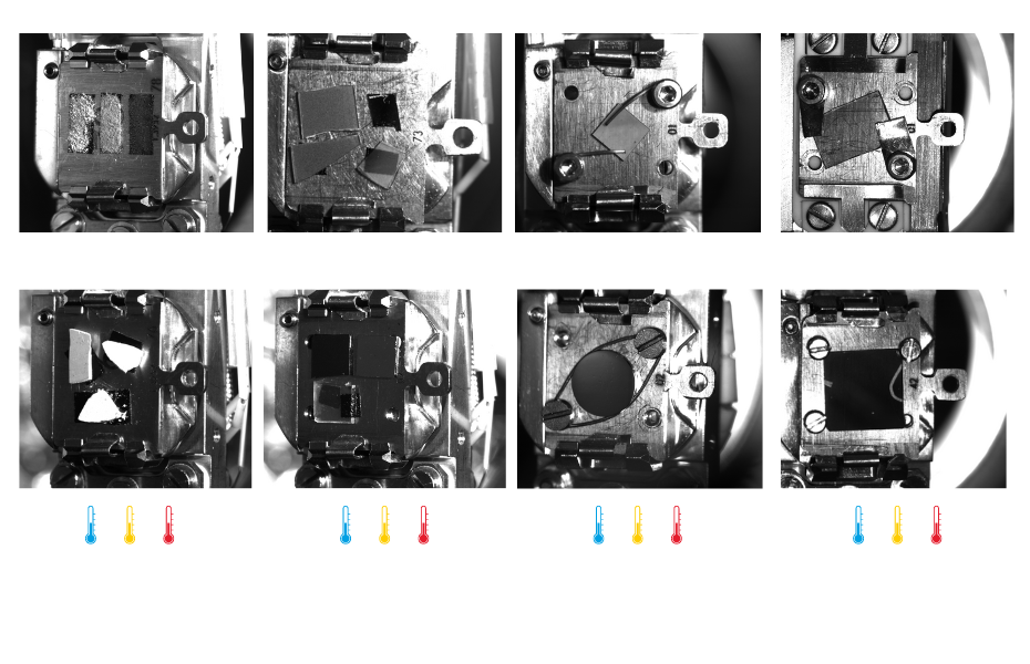
Figure 8. The examples of sample mounting on the holder. (a,b) The powder samples installed using carbon tape, (c,d) the single crystal or specimen deposited on substrates installed using carbon tape, (e,f) the single crystal installed using tungsten wires, (g,h) the sample installed using clamps or screws. Thermometer pictograms symbolize the measurement temperature ranges appropriate for a given sample assembly in a given column (blue – low temperatures, orange – room temperature, red – elevated temperatures).
Measurement geometry
The magnetic field up to 0.14 T along the beam direction can be applied. The sample can be rotated about the vertical axis +/- 100 degree in the centre of the electromagnet.
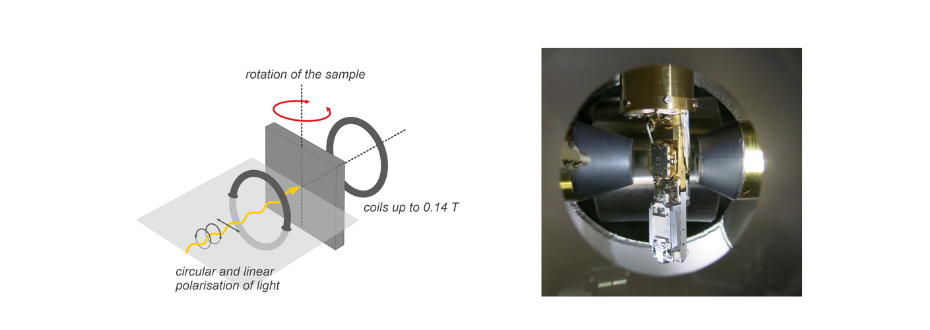
Figure 9. The measurement geometry relative to the photon beam axis and the electromagnet, (left) diagram (right) photo of the sample holder placed into the manipulator in relation to the electromagnet's yokes.
Preparation chamber
- 4 axis manipulator allowing colling to 150 K and heating to 1200 K (short flash to 2200 K);
- LEED/AES Spectrometer;
- Metal vapour sources (Fe, Co, Au, Cr, Ni) controlled with a quartz crystal balance;
- RGA
- Broad beam ion gun (Ar);
- Oxygen dosing system.