
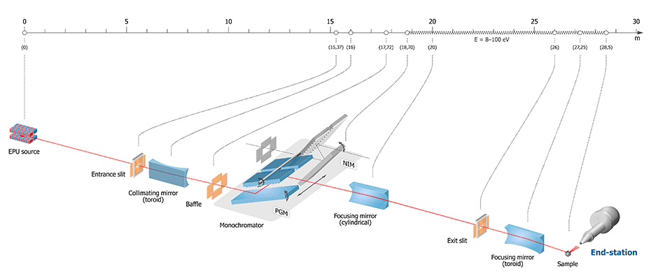
Figure 4. URANOS beamline layout
The first element of the beamline that generates electromagnetic radiation is a quasiperiodic elliptically polarizing undulator that produces any polarized beam of radiation in the ultraviolet (UV) and soft X-ray range. Then there are slits (horizontal and vertical) and a toroidal mirror M1 (16 m from the source), which collimates the beam vertically and focuses horizontally in the plane of the exit slit (26 m). And it leads the photon beam to the monochromator chamber (18.7 m) onto a mirror and diffraction grating system in a plane/grazing geometry (PGM - Plane Grating Monochromator) or a mirror and grating system in normal geometry (NIM - Normal Incidence Monochromator). The PGM monochromator works in the range of 12-600 eV, and the NIM in the range of 8-30 eV. Behind the monochromator chamber there is a cylindrical mirror (20 m) focusing the light in the vertical direction on the exit slit. Behind the exit slit is a toroidal mirror (27.3 m) that mirrors the image of the exit slit 1:1 on the sample surface in the analysis chamber at the end station.
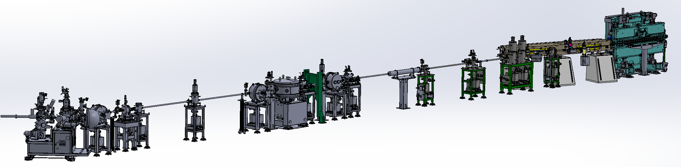
Figure 5. CAD model of the URANOS beamline.
Undulator
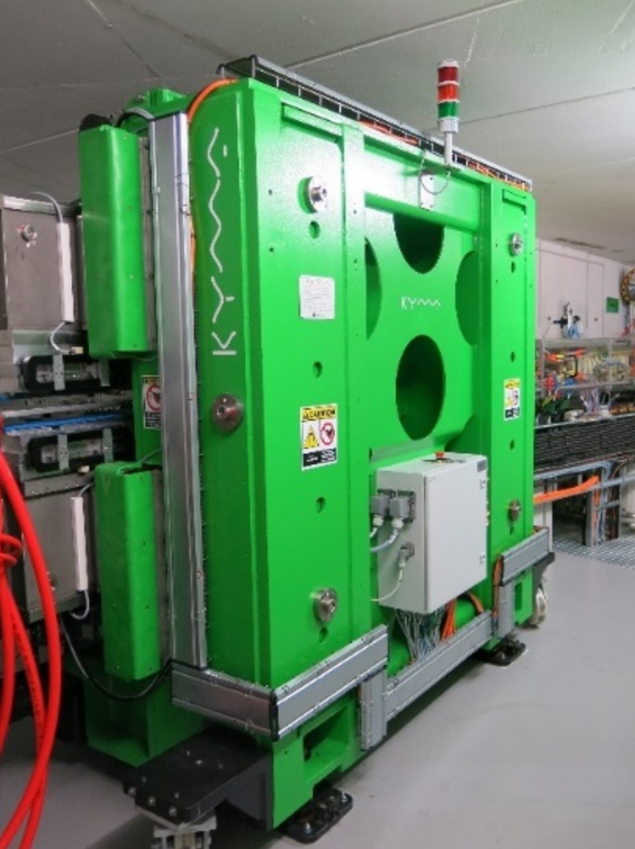
Figure 6. Apple II undulator - source of radiation for the URANOS beamline.
The source of synchrotron radiation for the URANOS beamline is an elliptically polarizing Apple II type undulator with a quasiperiodic magnetic field geometry manufactured by Kyma SrL. The use of such a magnetic field geometry enables a significant improvement in the spectral purity of the UV beam (weakening of harmonic components). At the end of the beamline, the contribution of higher harmonics in the spectrum of excitation radiation falling on the sample is less than 1%. The elimination of harmonic components in the spectrum of excitation radiation is particularly important for the ARPES technique because the aim of this technique is to map the band structure of a solid. The intensity of the experimentally measured bands depends on the probabilities of the optical transitions in the solid, and there are sometimes small. Moreover, the number of observed bands, especially in materials with large, polyatomic lattice cells, can be very significant. In this situation, both the increase in the background level and the presence of band replicas caused by the presence of harmonic components in the spectrum of excitation radiation may prevent the correct interpretation of the measurement results.
The Apple II undulator can generate any polarized electromagnetic radiation; the following polarizations are available: linear horizontal, linear vertical, all linear skew, circular right and left, and any elliptical polarization.
Exemplary measurements of dichroic effects in ARPES, caused by the dependence between the matrix elements of optical transitions and the direction of electromagnetic field vibrations.
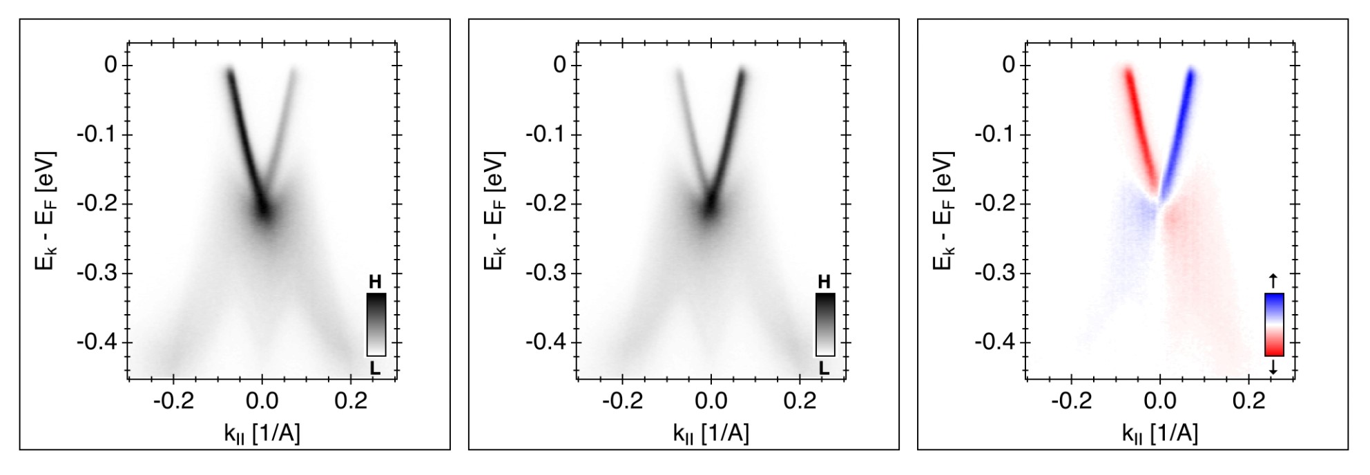
Figure 7. ARPES spectra showing the effect of circular dichroism on a Bi2Te3 sample for different polarizations (left, right and signal difference, respectively) polarizations for energy excitation hv = 55eV.
Insert device parameters:
| Parameter | Value |
| Insert device type | EPU Apple II, quasiperiodic, Kyma S.p.a. |
| Range of opening motion | 20 (min.:18 mm) – 200 mm |
| Magnets Saturation field Magnetic field amplitude Number of periods Period length (λ0) Total length |
NdFeB permanent magnets;
21; |
| Mods | Parallel and antiparallel |
| Polarization | All, full control of light polarization: linear, horizontal, vertical, skew, circular right and left, any elliptical. |
| Radiation power at full closure | 600 W (for current 500 mA) |
| Parametr | Max. 6.5 |
Monochromator
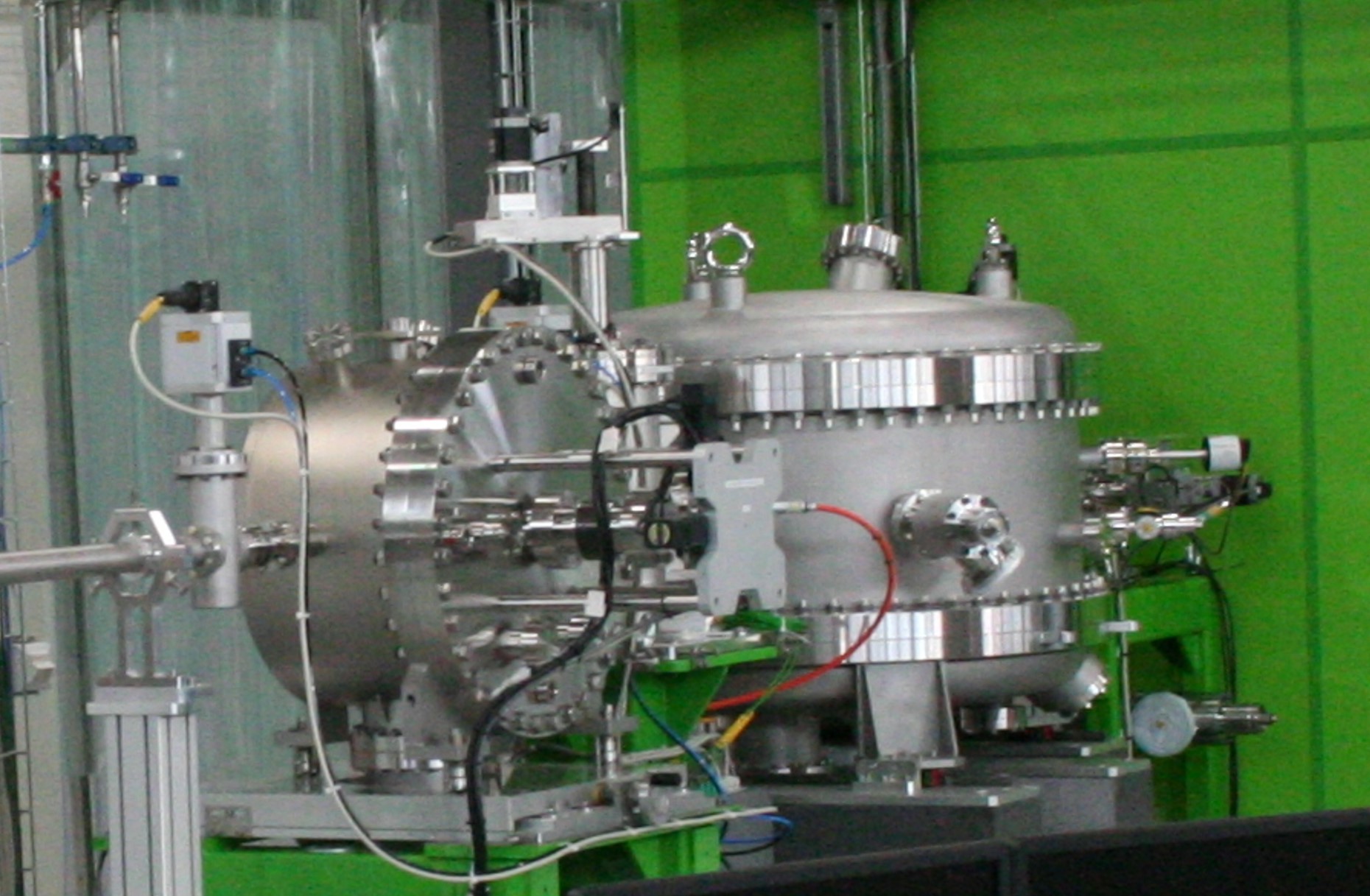
Figure 8. Monochromators (PGM and NIM) chamber at URANOS beamline and cylindrical mirror 2 chamber.
The monochromator chamber contains two optical systems; the first works in the plenary geometry, the grazing angle of incidence, PGM (plane grating monochromator), the second in the geometry of normal incidence, NIM (normal incidence monochromator). The PGM monochromator works with a grating with a line density of 600/mm, and the NIM with a grating with a line density of 2000/mm. These are the so-called laminar gratings, that is, those having a rectangular profile of grooves. The use of two different reflection geometries allows optimizing the parameters of the photon beam depending on the requirements: it can be, for example, maximization of the photon flux, maximum spectral purity of the beam, or minimal polarization deformation. The PGM monochromator works in the range of 14-600 eV, and the NIM works in the range of 8-30 eV.
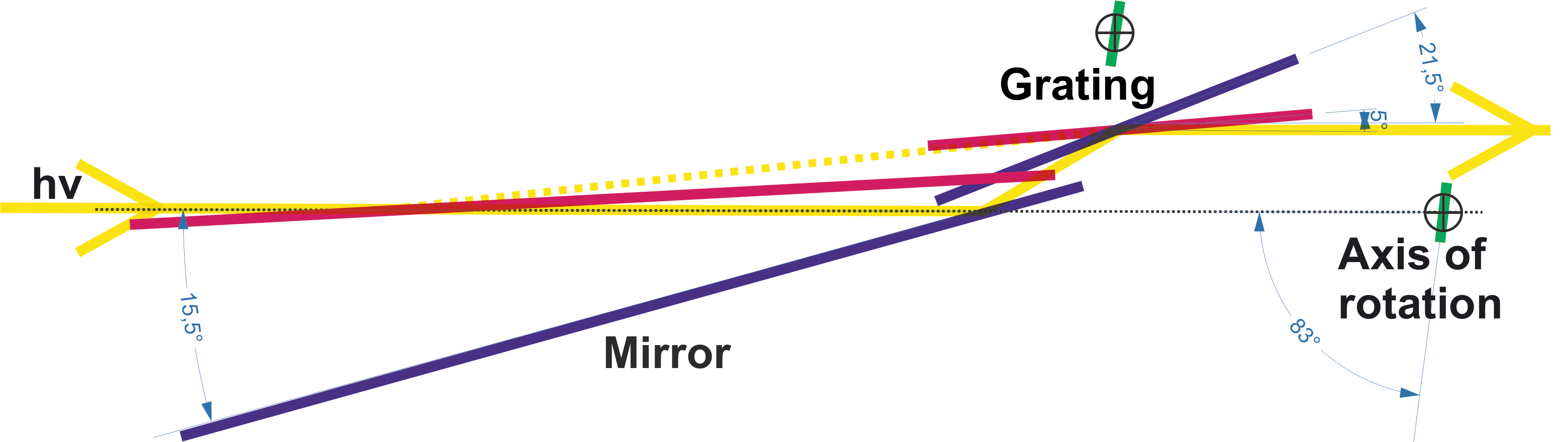
Figure 9. PGM monochromator geometry. The figure shows two positions of the grid and the mirror relative to each other for the allowed angles of rotation.
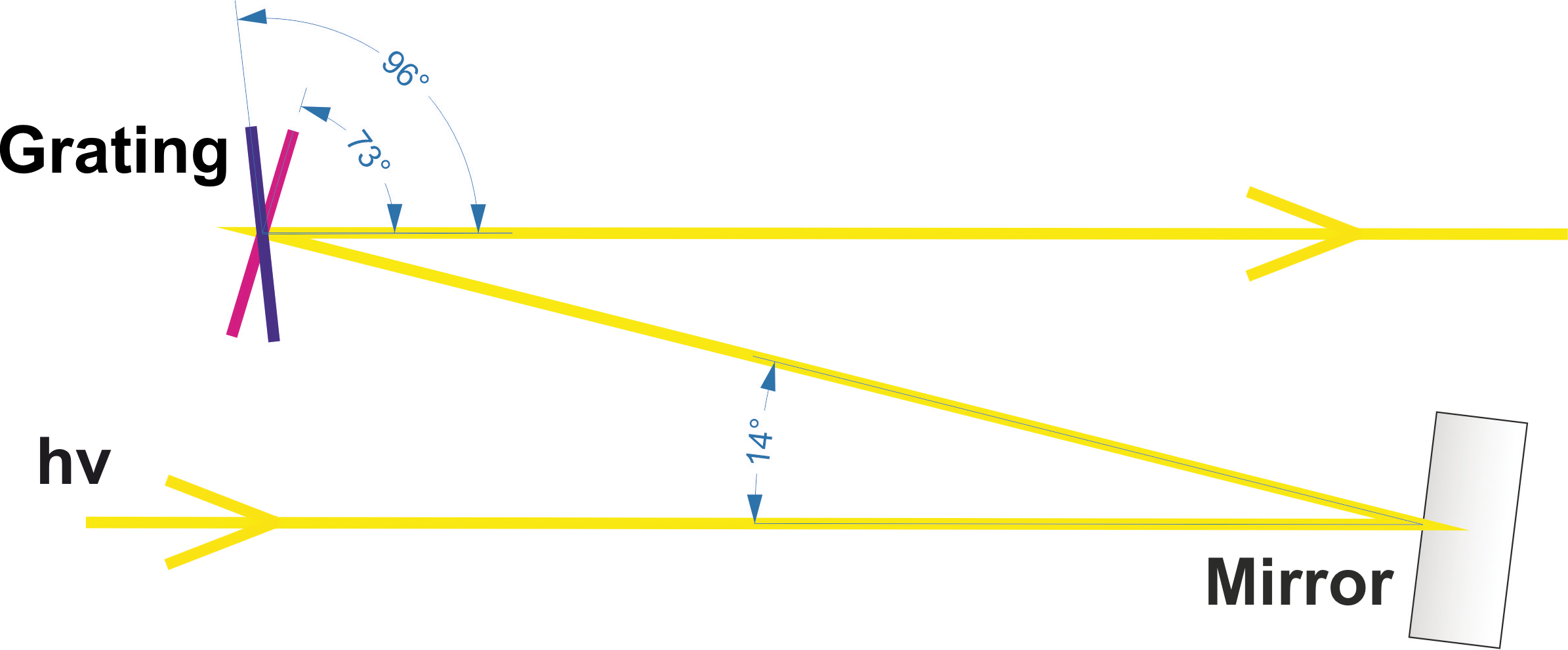
Figure 10. Geometry of the NIM monochromator with a static mirror. Two extreme positions of the monochromator grating are shown.
The beam coming out of the monochromator must be directed towards the stationary exit slit (in the horizontal direction), i.e. regardless of the selected energy, the beam must always be at the same height relative to the exit slit.
The wavelength of the radiation coming out by the PGM and NIM monochromator can be determined by the formula:

Where αn, βn are the angles of incidence and diffraction on the grating, respectively, measured with respect to the surface normal, N is the density of lines, grooves on the diffraction grating (for PGM 600 mm-1), and k is the order of diffraction.
For the grating working in the PGM mode, due to the variable angle of incidence (depending on the angle of the plane mirror), we also define the so-called constant cff (fix-focus constant):
The cff parameter has practical use. If very high resolving power is required, this parameter should be increased (maximize, α and β have a limited range), while if we minimize harmonic components, then we should strive for the minimum possible cff values, as this will allow for more efficient suppression of harmonic components in the monochromator.
Exit slits
The exit slits are equipped with a precise parallel slits opening mechanism.
Energy resolution (RP), depending on the size of the exit slit Δs_ex , exit angle β_n, diffraction order, etc. is defined as:
where q defines the distance between the focusing mirror and the exit slit and is 6 m. Hence, the contribution depending on the vertical exit slits gap to the energy resolution of the beamline can be calculated as:

The groove density N is 600 lines/mm for the PGM and 2000 lines/mm for the NIM. The angle βn denotes the diffraction angle on the monochromator grating, measured with respect to the surface normal. It can be expressed via the incidence angle αn as: cosβn =cff cos αn.
Total beamline resolution
The total resolution of the URANOS beamline can be defined as follows:

where ΔEsource is the contribution of the finite source size on resolution, ΔEexit slit is the contribution of the exit slit on the resolution of the photon beam, ΔEslope is the effect of the local slope errors of the optical elements of the beamline, and ΔEdiffraction is the diffraction limit for the exit slit for a given energy and is defined by the Raleigh criterion.
A macro for calculating the overall resolution of the photon beam is available on the beamline.
Beam Positioning System
Measurements on the URANOS beamline are largely automated and programmable. To enable this, a beam-position correction system is employed. The system operates by adjusting the angular position (roll) of mirror M3 (cylindrical mirror) in response to the difference in normalized currents from the horizontal plates of the exit slits:

where p → 0.The use of a PID controller enables tracking of the beam position and correcting it by adjusting the mirror position. Consequently, the system is adapted for automatic measurements, such as band-structure mapping as a function of excitation energy, i.e., so-called kz measurements.
Photon Flux
Downstream of the exit slits and mirror M4 (focusing toroidal mirror) is Diagnostic Station 4, equipped with a sublimation pump for differential pumping in the final section of the UV beamline before the photoelectron spectrometer chamber. An XUV-035 photodiode is mounted on the diagnostic manipulator and was used to measure the photon flux with the vertical slit set to 25 µm (250 µm) and the horizontal slit to 300 µm (500 µm) for the PGM (NIM) monochromator, across the entire generated photon-energy range, with a accumulated beam current in the ring of 400 mA. The obtained results are presented in Fig. X.

Figure 12. Flux recorded on diagnostics 4 before the end station.
Low-Energy UV Branch for Special-Purpose
In 2024, a chamber was installed and commissioned, equipped with a flat mirror set at a 45° angle to the photon beam axis. It's enabling the use of low-energy radiation for applications other than photoemission spectroscopy. The flat mirror is installed between the refocusing mirror and the exit-slits, it's mounted on a linear shift mechanism (LSMT) that allows precise positioning along the photon beam axis. The mirror deflects UV/VUV radiation perpendicular to the primary beam axis toward an MgF₂ window, directing the UV/VUV light outside the chamber. The system allows for the connection of other experimental chambers via a CF 40 DN port, including both low- and high-pressure chambers.

Figure 13. Flat mirror chamber and mirror holder on linear shift.